Relief Cut Sheet Metal
Http Files Engineering Com Download Aspx Folder B0283dfb F6a8 4c7c 8207 Eb6510b27548 File Sheet Metal Design Considerations Pdf
Gap Or No Gap On Sheet Metal Bends Mechanical Engineering General Discussion Eng Tips

Auto Vs Corner Relief In Solidworks Sheet Metal
Sheetmetal Not Able To Make A Box Correctly Please Help Autodesk Community Fusion 360

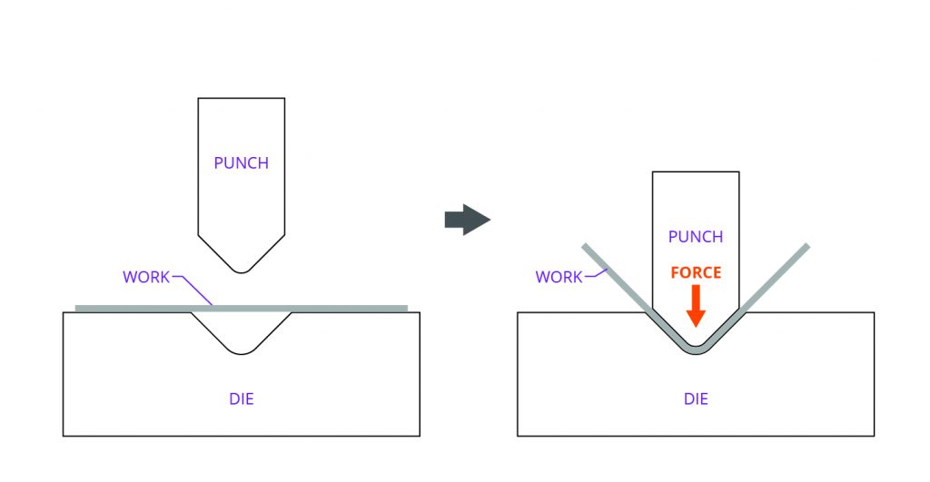
Sheet Metal Process Ultimate Guide 2019 W Cost Examples
Sweet Relief How To Avoid Hole Distortion In Sheet Metal Parts
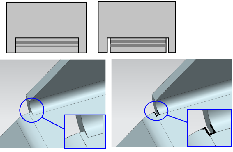
For example if you make a partial flange as above using all the defaults the software makes relief cuts at the end of the bends as shown to the right.
Relief cut sheet metal.

Layout And Forming Part Four

How Sheet Metal Corner Reliefs Are Applied To The Body

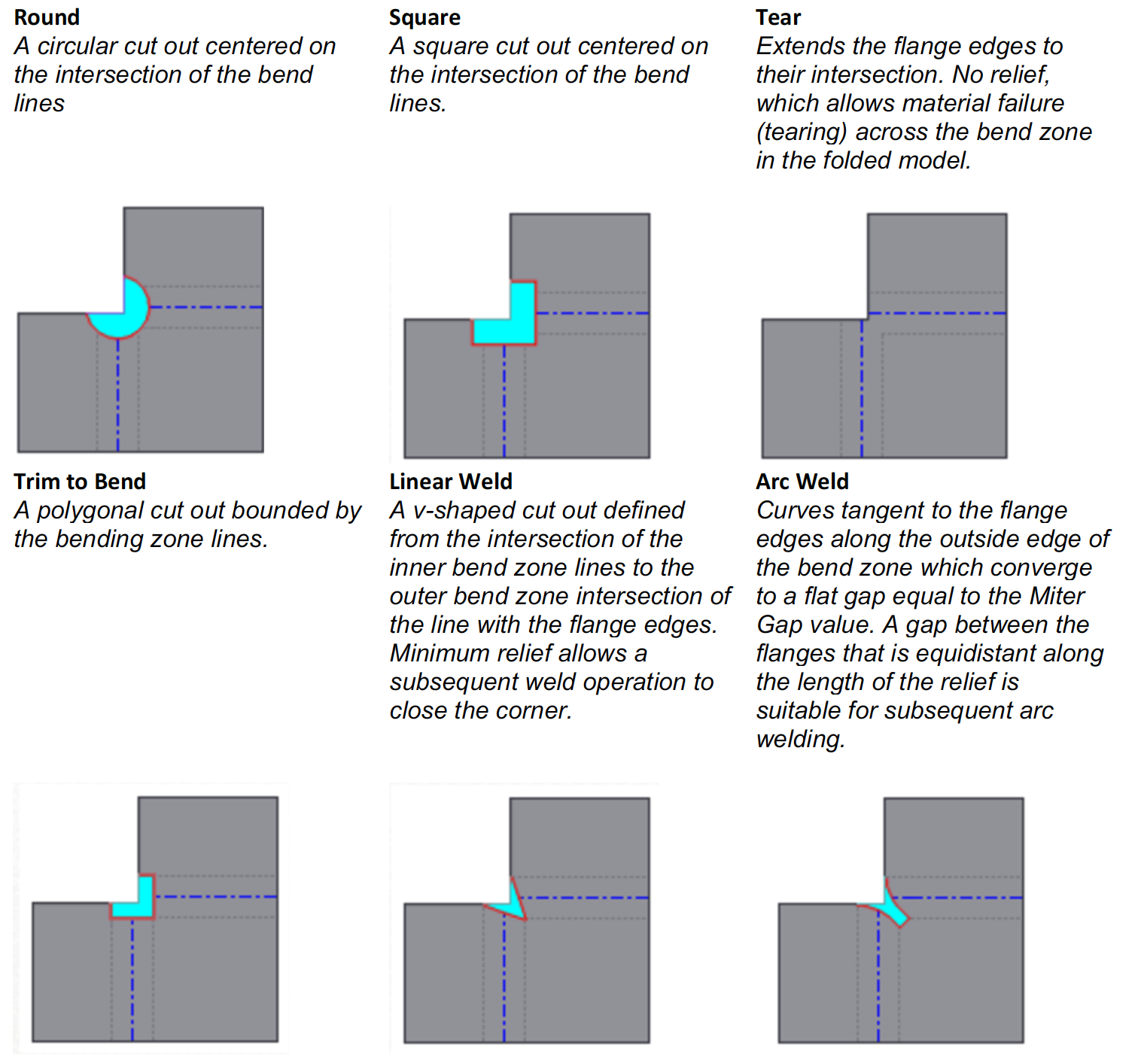
Sheet Metal Corner Relief Options
Https Cdn2 Hubspot Net Hubfs 340051 Design Guides Xometry Designguide Sheetmetal Pdf
Source : pinterest.com
